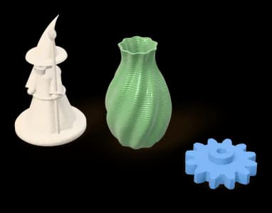
What the machine is doing
Fused deposition modelling pushes a thermoplastic filament through a heated nozzle and lays it down as a bead, one plane at a time. The bead is typically wider than it is tall, and it fuses to the bead beside it and to the layer beneath while both are still hot. Almost everything you need to know about designing for FDM comes from that description.
It is the process we run here. Parts are printed on our own Bambu Lab P2S and X2D printers — both enclosed, and able to run engineering filaments as well as everyday ones. Because the machines, profiles and slicer are all ours, every part can be priced instantly from a real slicing run.
The three settings that decide the part
- Layer height — how tall each plane is. Halving it roughly doubles machine time and visibly improves curved and sloped surfaces. It does very little for dimensional accuracy in the build plane.
- Wall count — how many beads make up the perimeter. This, not infill, is what carries load in a printed part. A part that needs to be stiff wants more walls before it wants more infill.
- Infill — the lattice inside. Above roughly 40 % the returns fall off sharply while time and material keep climbing.
On this platform these are not free sliders. They are properties of the profile the slicer will actually run, and the configurator offers only the profiles installed on the machines that would produce your part — so what you order is exactly what gets printed.
Where FDM wins
Decor and gifts, models and figures, organisers, jigs and fixtures, brackets, enclosures, ducting, fit checks and replacement parts. Anywhere stiffness, dimensional stability and turnaround matter more than surface finish or very fine detail. It is also the cheapest way to find out that a design is wrong, which is worth more than it usually gets credit for.
Where it does not
Transparent parts, features finer than the nozzle can resolve, show surfaces that must not reveal layer lines, and parts loaded hard across the layers. For those the usual answer is a resin or powder-bed process; we do not run those, and the guides explain them. Often a design change — a load path that follows the layers, or a matte carbon-fibre grade that hides layer lines — takes FDM further than you would expect.
The one number people misread
A process-typical tolerance — around ±0.5 mm for FDM here — is what the process usually holds on ordinary geometry. It is not a guarantee on your part, and it is not an inspection result. Tall thin features, large flat spans and parts that fight warp can drift further. If a dimension has to be right, design clearance into the fit and try a single part before ordering many. If you have a question, write to us.