What to expect from FDM
The typical tolerance for FDM here is around ±0.5 mm — the same figure the FDM process page shows from the live catalogue. It is what the process ordinarily holds on ordinary geometry: a planning figure, not a guarantee for every feature. Tall thin features, large flat areas and materials that tend to warp can drift further.
Design the fit, do not just specify it
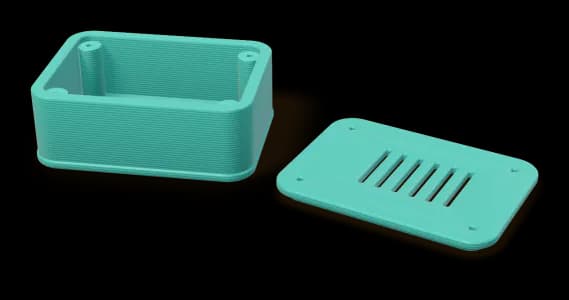
On most parts only a few features really have to fit: a hole for a screw, a clip, a lid. Put your effort there. Give sliding and push fits deliberate clearance (see Design rules for FDM) and leave the rest of the part free.
When a feature needs to be tighter
Printed geometry is good at shape and weaker at precise round holes and flat mating faces. If a feature must be more accurate than the print, the reliable route is to finish it after printing: print holes slightly undersize and drill or ream them, flatten a mating face, or use heat-set threaded inserts instead of printed threads. We do not offer this secondary work ourselves, but it is usually a simple job with ordinary workshop tools.
If you enter a tolerance tighter than the process typically holds when you configure a quote, the quote flags it straight away, so you can adjust the design before ordering.
Orientation affects accuracy too
Accuracy differs along the build axis and across it, and so does strength. The part is printed the way your file is oriented; an automatic search scores other orientations and records them on the quote as a recommendation only. If one round hole matters most, it usually prints best with its axis vertical, so it comes out as a true circle rather than sagging at the top.
Prove it with a test part
Parts are checked visually before they ship; we do not provide measurement reports. For a part that has to fit something else, the most reliable approach is to order one, try it, and adjust the design before you order the batch.